Showing posts with label Building A Diorama. Show all posts

Wednesday, May 9, 2012

Let's Build a 3D Card Model - Step 4 -- Conclusion

If you have been working along with the first 3 Steps you will have four walls and two roof sections.  Now is the time to do any cleanup around the door and window openings.  Check the corners for fuzzy card residue and use your knife blade to remove. 

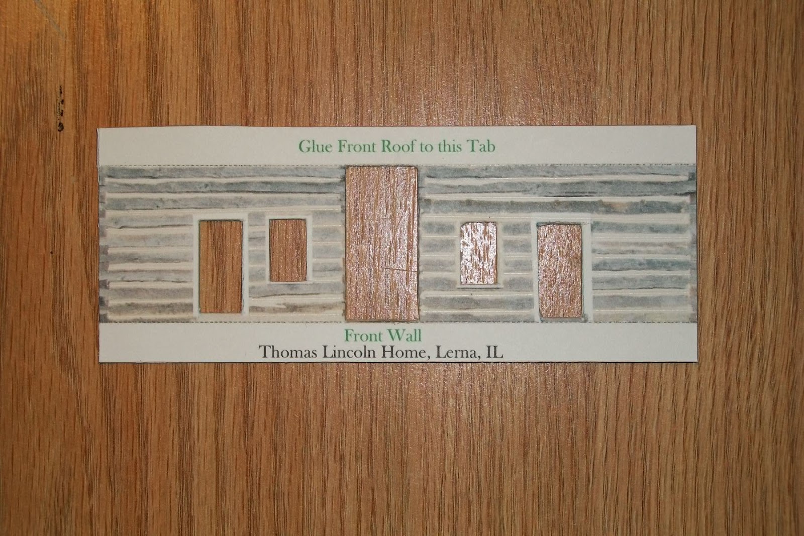
Front wall with cutouts complete and tabs folded'

The two end walls have no cutouts so just fold the tabs.
Take a lead pencil, and from the INSIDE of the door and window openings, use the side of the lead to darken the paper and card backing to eliminate any white spots.  Do it from the inside so if the pencil slips you won't get pencil marks down the face of the building.  Ask me how I know!  Also apply lead to all the edges of the walls and roof sections from the INSIDE faces.


A few problems came up during the assembly:
a.  The chimney is too small to fold easily when glued to the card backing so if you have not glued your sheets to the card cut out the area around it and set it aside.  The best solution is to print the sheet with the chimney and fold as a single sheet of paper.
b.  The tab on the one roof section is too thick to match the other side so I cut the tab off and made a paper hinge to replace the tab. Lay the two roof sections peak to peak (check the position for the chimney) and glue the hinge in position over the seam.
c.  This would be a good time to do something I forgot to do, paint the underside of the roof sections that overhang the walls.  Almost any dark color, tan, brown, black, looks better than the face of the cereal box.
d.  Some of the tabs (mostly at the ground level) need the corners trimmed back about a 1/16" and then at 45 degrees to clear he  tab of the of the mating wall.  I used a small diagonal cutter to trim the tabs, but the knife will do the job just as well.

 To mount the doors and windows recessed into the wall we need to add some spacer strips to the inside of the walls and mounting strips to the back side of the doors and windows. To do this use some of the left over mounted print and cut 4 or 5 strips about 1/8" x 3", holding the steel rule tightly to prevent slipping.

1/8" x 3" strips for mounting the doors and windows.


Study the picture below for a moment.
Using the strips we just cut, trim and glue them to the inside surface surrounding the cutouts, both sides of the 2 big center board wall cutouts, both sides and top of the 4 blue doors cutouts and both sides, top and bottom of the 2 window cutouts.  Align the strips to the edges of the cutouts and use just a couple little dabs of glue.  These strips create the spacing to recess the doors and windows.

Now cut strips about 1/4" longer than the width of the doors and windows and mount to the rear (inside) surfaces with a single little dab of glue.

Spacer strips and mounting strips applied and drying.
When the glue had dried dry-fit the windows and doors in the cutouts and behind the spacer strips.  This is the time to ensure you have the right item in the right cutout.  Also note that some have top or bottom details that must be correct; the big center board walls have weathering at the bottom edge and one window has a person's silhouette.  When satisfied with the fit and location, mount the cutout items with a single dab of glue on the 4 protruding tabs and set aside to dry.
Doors and window located and mounted in the wall sections.

At this time you can take a look at the 3D effect you have created.  If you built the model in Step 1 compare the flat surface with the recessed surfaces.

We are now going to do the final dry-fit of the 4 walls.  check each corner to ensure the tabs don't overlap or interfere with each other.  If you have a small desk drawer you can use the inside corner of it to ensure a square corner and same height where two walls meet.  I cut several right angle triangles with about 3/4" long legs. and glued them as gussets in the corners to keep the structure square.

With the 4 walls complete, fit the roof to the walls and determine how much overhand on each end.  Apply glue along the tabs, locate the roof over the peak of the side walls and hold in position pressing on the end wall tabs to let the glue tack.  Now turn the house over on the roof and press the side wall tabs against the roof, both sides.

The chimney is the last item to mount in the location noted on the roof panels.  Scrape a little glue to the inside of the mounting edges and a very little to the edges and set in place.

Here I am comparing the 3D model with the flat surface model I built earlier.

You now have a substantial model in HO scale, 1:87.  Place it on your HO model railroad, or on the shelf for others to admire.  I am already thinking of a little diorama with a split rail fence, outhouse, well, woodpile, maybe a cow or pig...............

Till next time,

Armchair


Saturday, May 5, 2012

Let's Build a 3D Card Model - Step 3 -- Cutout Details

In Step 1 we downloaded the two free colored  sheets of the Thomas Lincoln house and built the house per the instructions provided.

In Step 2 we mounted the second set of printed sheets to the cereal box card stock.

In step 3 we will begin cutting out the several sections of the building.

Just a reminder, this is a first for me, cutting out details such as doors and windows and mounting them set back from the outside surface of the model, creating a 3D appearance.  Do not expect perfection, we will be learning together.

WARNING:  Tools used in card modeling can cause injuries if not used carefully.  Children should proceed only under adult supervision!

Tools:  In the photo below you will see the tools needed for this part of the project: a knife handle with a #11 blade or other knives with break off or replaceable blades, a steel rule toguide the knife blade, a small hammer and nail or straight pin to locate the corners of the doors and windows.  Not shown is a letter opener I use to scribe the fold lines.

Tools and mounted, printed sheet, ready to make your 3D model.

Note:  You may wish to practice the several action OP's described below using the extra space around the sheet.

OP. #1  Scribe the fold lines with the letter opener using the steel rule to guide and ensure straight fold lines.  Without the cardboard backing this could be done with 3 or 4 firm strokes, but with the card backing I found I also needed to use the knife blade to cut about half way through the backing.

OP. #2  Place the mounted sheet over a scrap of cardboard or foam core to protect the table surface.  Carefully place the point of the nail or pin at the corner of each door or window detail to be removed and use just a light tap of the hammer to pierce about half way through the cardboard backing, just enough for you to locate the point of the knife blade.

OP. #3  Place the print on your cutting board and use a steel rule to locate the cutting line between two corner punches, check each location with the blade point, and while holding the steel rule firmly, lightly stroke the knife blade between the two punches several times. Repeat for each side of the door or window and, with firmer strokes continue cutting until the door is cut free.


Two doors and windows and the center board wall have been removed.

OP.#4  After all the scribing and cutting is complete remove each part by carefully cutting around the part being sure to NOT cut off the fold tabs.  This will leave you with a part shown below.


Cutout front detail part before folding the tabs.


OP.#5  Locate the fold lines at a sharp edge and fold tabs down as shown below.  If the tabs don't bend with firm pressure you may have to use the knife to cut a little deeper into the backing sheet.

Front detail with tabs folded down.

Continue with other details, back, sides and roof, until you have all the parts required for the model.

This is one of the end details with tabs folded.


Details ready for adding the recessed doors and windows for a 3D model

In Step 4 we will be adding the recessed doors and windows and maybe some outside raised details.


Armchair

Friday, April 27, 2012

Let's Build a 3D Card Model - Step 2 -- Add Cereal Box Backing

If you downloaded and built the house in Step 1, you will need to print another set to complete Step 2 .

A.   To add strength and thickness to the model I am going to mount the downloaded sheets to heavier card stock, a cereal box.  I found a box large enough to mount the letter size, 8.5"x11", sheets.

When you card model you save boxes like this.  If you have kids you already have a ready supply.


B.   Cut open the box along the sides to obtain something like this.

Two long cuts and two short cuts provide the basic material.  Save the small, leftover parts for details to come.


C.  Cut out the front and back panels, trimming the edges to ensure a flat surface.

Here are the panels needed to mount the printed sheets.  This slick, outside surface is sealed enough for Yuma, but you may want to seal both sides with spray primer.

 
D.  Here in Yuma, Arizona we have mostly low humidity so I use the cereal box as is, leaving the printed outside surface on the inside of the model and gluing the printed sheet to the bare inside surface.  If you want to protect your model from warping with damp / dry conditions you may wish to seal both surfaces with a spray primer.
These card panels are now ready for the spray adhesive.


 E.  Use a spray adhesive to give the bare surface of the card a light even coat, locate the sheet and smooth out using a stiff ruler.  I just happen to use a tile trowel that I have around.  Leave over night under weights to ensure the panels dry flat.

WARNING: Spray paints and adhesives should be used outdoors, away from flames and with a backdrop to collect the over-spray and protect other surfaces.

All for tonight.  My panels are drying under weight and I will edit this step 2 over the weekend.  Then we start with scribing the fold lines, cutting out the details and folding the corners.

Armchair

Wednesday, April 25, 2012

Let's Build a 3D Card Model - Step 1 -- Free Internet Download

Card modeling is an old craft with a new life.  Old timers like me will, if able, remember cereal boxes with the back printed with some toy or building.  We would cutout the item, fold on the lines noted, push the tabs into the related slots, resulting with a free toy.  With WWII over "real" toys came back on the market and card modeling in the USA fell from favor.  Europe must have spent a few more years with material shortages and card modeling held on with a newer generation.
Now, with the internet, card modeling has surged back with both free and commercial sites offering thousands of models of every imaginable type.  For this little build clinic I have chosen a free American model of a log cabin once belonging to Thomas Lincoln, President Lincoln's father.  This is one of the Build Your Own Lincoln Sites, available at 
 www.lookingforlincoln.com

The completed model is shown with the two pages downloaded from the internet and printed on 110# card stock with a color printer.  The models in this series are 1:87,  HO scale.
I have wanted to try adding depth to a printed model by recessing the doors and windows and applying the shingles row by row, creating a 3D model.  This may require printing a second and possibly a third copy to have enough extra parts to complete the modification.

But for now, go to the site noted above, and even if you have never built a card model, download, print and build the model using the instructions included.  Don't worry about making a mistake, just print another sheet if needed.

TIPS:  You can use scissors or craft knives to cut out the several parts of the model.  When using a knife make several light strokes instead of one heavy stroke.  Paper dulls knife blades quickly so keep a supply handy.  Most modelers use the #11 blade that fits a small handle.  I use a letter opener to score the fold lines making several moderate passes.  Practice will help you develop the skills and improve your results.

WARNING:  Knives and other tools used in card modeling can cause injuries if not used correctly.  Children should proceed only under adult supervision.

Check back often for updates of the 3D modifications and hints, tips and additional sources for help and information on card modeling.

See you soon!


Armchair


Wednesday, July 13, 2011

Building a Diorama - Part #10 - Surgery

SURGERY:
I hope you are over your fear of change.  As I said in my fit of rage (Part #2) I took the scissors and hacked the middle section of the 'finished' diorama from top to bottom, leaving the track section and a small section at the top to hold the two halves togetherHere are the before and after pictures.
A nice, simple, finished diorama.


A chopped up diorama.


I am going to follow this up with a series of pictures showing step by step how I CHANGED / EVOLVED this simple diorama into a more dynamic and photogenic railroad setting.


My first action was to strengthen the top connecting section by wrapping with plaster cloth.  I then covered the rough edges with plaster cloth to connect them to the profile boards.  To allow shaping the ravine i added 1" extruded foam to the sides and bottom using acrylic caulk adhesive.  Note the pill bottle wedges and the carved out front edge for the little, almost dry, creek bed.  A sharp eye will notice I was still experimenting with  ground coloring.


This picture shows more detail of the use of plaster cloth, extruded foam and pill bottles.  Not seen is the ledge I cut into the blue foam under the track roadbed to provide a base for the 1" high end bents for the pile trestle bridge I will be adding later.  Also note the high level of expertise used in cutting the foam and expensive tooling involved.  As they say on TV, "Don't try this at home, I am a professional."  The exam to attain this 'professional' level is to JUST DO IT!


Here is another view of the high level of expertise required to achieve this finely crafted diorama.  I simply used what was available at the time, newspaper, pill bottle and scrap blue foam, stuffed into place to hold the conture required.  As stated before, a clean and neat work area is a necessity to achieve professional results.


Now you see the ravine shaped by adding a back wall of blue foam and plaster cloth, supported in the rear with newspaper and scrap foam pieces.  The sides and bottom were shaped with a rasp and painted with several thin coats of lightweight spackling thinned with water.  The plaster cloth areas were painted in a similar manner to blend into the existing scenery.


This low angel view gives a better perspective of the finished ravine and the area to be bridged.  The two ledges are also visible on either side below the roadbed.  The white color will accept color in the next series.


This shot is to show you the type of jig I used to build the bents for the trestle.  It consists of a piece of foam core board with a center line drawing of the pile and cross brace locations taped in place.  I covered the whole thing with a cutoff sandwich bag and used straight pins for locators.  I will have a better diagram in the later part about Driven Pile Bents for Trestles.


The evolving ground coloring proved too close to the rock outcrops and will be changed.  The pile bents are laid out to show their detail, most of which will be hidden once they are installed.  The wet trickle of water maintains a little growth of questionable quality and was created by dribbling several layers of grey, blue, green and yellow down the back wall and let run to the front.  Several coats of gloss poly helped give it the wet look.

The bents are now installed and support the roadbed.  All that remains is to install a few braces and touch up the ground coloring to be more in contrast to the rock carvings.


Finally we see the mostly completed diorama, backed by the mountain and sky boards, used as a setting for a little engine and caboose.  Still need to add some scrubby plant life and better contrast between the rocks and ground.  Yes, it is still evolving.

Tuesday, July 12, 2011

Building a Diorama - Part #9 - CHANGE

CHANGE:  "The more things change, the more they stay the same."  anonymous

Building a model railroad is almost like being a god.  We get to create it anyway we wish; big or small, old time or modern, steam or diesel, city or rural.  But, unlike God, it is not perfect, we see defects and ways to make it better.  We see the need to CHANGE!  BUT, look at all the Effort I put into this!  All the Money!  All the Time!  To CHANGE a CREATION is sacrilege!  So, maybe we aren't ready to be gods!  Maybe WE should consider EVOLUTION!  We start out small and simple, add a little here and there, get more room, find more money, learn new skills.  All this prepares us for the dreaded CHANGE!  But wait, from the beginning this layout has been evolving, and evolution is change.  See, now change is not so big and threatening, it's just a little thing.  Now change is something we can cope with and someday even embrace.

Here is a little about the changes I made, or better, how my diorama evolved over time.

Just starting out with Foam-Core Board and string.
The shape take form with Plaster Cloth.
Some paint makes it start to come alive.
Rocks take shape with Lightweight Spackling.
 

Building a Diorama - Part #8 - An Interlude

An Interlude:
For those of you who have been following this Blog it may be time to press the pause button and look back a bit to Part #2 - Finding Your Setting.  For newbes, that little tirade about change will expose you to an insight into how I approach things, consistently procrastinate until you explode with 'whatever.'  Another insight might come with my blog of June 16, 2011, Who Am I?

I guess a better title would have been "The Lull Before The Storm."  I might be described as an enigma, not exactly what I seem to be.  The cool, confidant, intelligent individual is not exactly who I am.  I grew up with change, 12 addresses by high school graduation.  I have lived my adult life with change, 50 more addresses and 35 jobs of several descriptions.  I have never been settled long enough to have a permanent layout, never learned to get "really" organized, never really learned to make close friends.  At best you could say I live in the present and the past, my future is unknown, sort of a "Doctor Who" type of person.

So back to modeling.  I like to experiment by doing things a different way, yet one of my favorite sayings is "Don't reinvent the wheel!"  That is why this Blog was started, using foam-core board, because the model railroad community consensus was that the material was unsuitable for model railroad construction.  What a challenge!  If you have sauntered off to other model railroad sites you may notice that I am not a "really, really" good modeler.  I believe in caricature, point out the obvious - if it walks like a duck and quacks like a duck, it is a duck.  Therefore, if it has engines and cars like a railroad, and moves around scenes like a railroad, it is a railroad!  The funny thing is, most people agree with me, maybe not most 'real' model railroaders, most people.  What I am trying to achieve is a step up from a bare plywood board and helping a modeler who may feel all alone in the wilderness.  I want the modeler to gain the confidence to build a little layout, add some track and scenery, run some trains and impress your friends (and yourself) who thought you could never do all that.  So with this in mind let us go into the holy of holy's, the layout, and rent the scenery in two and change the scene.  On to Part #9 - CHANGE!

Monday, June 13, 2011

Building a Diorama - Part #7c - Basic Ground Cover Application

Basic Ground Cover Application:  As we progress on our Diorama you may see that it is becoming more of an Art rather than a Science.  Where at one time we had measured drawings, we now have a handful of this and a squeeze of that.   And remember, Art is in the eye of the beholder, and we don't all behold things the same way.  Be prepared for someone to say "That doesn't look like a rock to me!"  It is your Diorama and if you someday say "He's right, it doesn't look like a rock!", you can always change it.  It isn't chiseled in stone, only plaster cloth and spackling.

To apply our Colored Sawdust Ground Cover to the Diorama we may use most common adhesives.  I like to use a Yellow Wood Glue, thinned about 2 parts water and 1 part glue, mixed in one of my empty Pill Bottles. Select an area on the diorama where you would like some Grass or Weeds, select a suitable color and size from your Course, Medium or Fine, paint the area with the thinned glue and sprinkle with the ground cover.  Cover well as the excess can be vacuumed off.  Repeat as desired with color and size to suit.  If you decide it is not good, scrape it off and try another combination, until you can say "That is good!", and then rest.

What I have described so far in 7a, 7b & 7c can also be used with sandy dirt, dried leaves and grass, tree bark, almost anything that can be ground to a suitable size.

By now you have a Diorama structure built from Foam-Core Boards, covered with Plaster Cloth, textured  with Lightweight Spackling and some house or craft paint, a roadway or path running through, maybe some rocks laid in, and finally planted with various colors and sizes of grass and weeds.  It looks GREAT!  Just what I wanted!  No changes needed!  Well, if I were to do it again I might want to change this a little, and not try that again, that color is a little off and "That" doesn't look like a rock.  Welcome to modeling

This might be a good time to review the earlier posts because Part #8 will be about how I changed my diorama, and, I think for the better

Building a Diorama - Part #7b - Basic Ground Cover Sizing

Basic Ground Cover Sizing:  Now that we have produced a variety of colored sawdust it is time to sort the products into usable sizes, ie, Course, Medium and Fine.  For this I use two tea strainers, one finer than the other.  This can be a bit messy so use the cookie sheet as your base.  Place a spoonful of one colored sawdust into the course strainer, shake lightly and use your finger or spoon to work the sawdust through the strainer until little more goes through.  Dump the remains into one of your small container - this is your Course.  What has sifted through is Medium and Fine.  Continue sifting until you have sifted all your first color and dump the tray into a container.  Now take the finer tea strainer and repeat the operation with what sifted into the tray, dumping what remains in the sifter into a second small container - this is your Medium.  What has sifted through into the tray is your Fine, now stored in the third small container.  You now have three small containers of one color green sized into Fine, Medium and Course.  This simple procedure is repeated for each color you have selected.   Note:  I often re-sift the Course and Medium to collect more Medium and Fine.

Sunday, June 12, 2011

Building a Diorama - Part #7a - Basic Ground Cover Production

Basic Ground Cover Production:  There are several commercial sources for ground cover scenery material, but I am going to describe how I, and you, can make your own from sawdust or ground foam.   While I have not used ground foam, the process is very similar to that of sawdust, though foam must be ground in a blender to produce the small size required.  Most find their source of foam as scraps at upholstery shops.  I find my sawdust in my wood shop or a local lumber yard.  A couple of coffee cans will keep you going for quite a while.  Try to find common pine or fir dust and stay away from treated or exotic  woods because of possible toxic reactions and colorful stains.

 Supplies:
  • Sawdust
  • Craft paint in several green colors
  • Tea strainers
  • Quart jar and lid
  • Cookie sheet or cake pan
  • Several small storage containers with lids
  • Some old pill bottles


 Note:  For supplies I go to "dollar" type stores and haunt the kitchen area for cheap items.  This is easier than using your mates "good" kitchen items and having to replace them with quality items.  (spoken from experience)


Procedure:

Place a loose handful of sawdust in the quart jar.  Place about a quarter cup (2 oz.) of water in a pill bottle, squeeze in some green paint, cap and shake.  Pour the paint solution into the sawdust, screw on the lid and shake, shake, shake.  If the mixture is too dry add more thinned paint, if too wet add more sawdust.  In a few minutes you will have a somewhat consistent color.  Pour the contents onto the cookie sheet to dry.  I like to place mine in the oven, preheated to 150F, to speed drying and also kill any bugs, etc.  Now repeat with the other colors and save in your storage containers.

Friday, June 10, 2011

Building a Diorama - Part #6 - Rough Terrain

Rough Terrain:
Now is the time for all good modelers to lift their Dioramas high and note how light they are.  This is the main benefit of using Foam-Core Board You have now created a very strong, but light weight structure, at a cost of somewhere between $3.00 and $9.00.

This is also the time to install the Roadway Board into the roadway cut into the Profile BoardsDry-fit the roadway into the cuts and check the ends.  If too short you may need to add a small piece of foam core board on the inside of profile #1 and #4, even to the cutout.  Trim the roadway to suit, add glue to the edges of the profile boards and press the roadway into place.

Over the years modelers have used a number of ways to produce the base for terrain, card strips, wire screen, wadded-up newspaper balls, etc.  As you can see from the picture I went my own way and used twine.  


This picture shows my roadway in place and the twine laced between the Profile Boards that will support the Plaster Cloth added in this step.


You might choose to use some type of tape or paper strips glued to the boards to produce the base for your rough terrain.  I would suggest stuffing wadded-up newspaper between the boards to better support the twine or whatever you choose.  These can be removed after the plaster cloth has set.  And remember, you can always change your mind.


This is what mine looked like after applying the plaster cloth.


As you can see by the picture you will need a shallow pan or dish for water to dip the plaster cloth pieces into before spreading them on the support forms.  If neatness counts you may want to place a plastic table cloth under this operation.  Start by cutting about 10 or 12 pieces of plaster cloth about 8" long.  Briefly dip a piece into the water until wet, let it drip a second or two and lightly place or drape over your structure.  Repeat with additional pieces, overlapping them about an inch, until you have covered an area.  You may smooth the cloth with a wet finger or bristle paint brush.  Add a second or third layer to achieve a strong, firm base for your scenery and ground cover.

After the cloth has dried and you are satisfied with the firmness of your scenery base, you may notice a grid like pattern of the cloth.  You may try to smooth it out with a wet bristle brush or paint it with a couple coats of latex house paint.  Try to choose an earth like color.

You now have a lightweight structure with a thin shell form that is ready for your basic ground cover.  For that we will go on to Part #7 - Basic Ground Cover.

Monday, May 30, 2011

Building a Diorama - Part # 5 - Erecting The Profile Boards

Erecting The Profile Boards:
Now that we have our Base Board, Profile Boards and related Gussets, Front & Rear Edge Boards cut we are ready to begin building the diorama.  Get your #1 through #4 Profile Boards oriented to the #1 through #4 positions on the Base BoardGlue 2 Gussets to each Profile Board at the bottom edge where they will meet the Base Board, located about 2" in from the rear and about half way front to back.  Be sure that on Profile Boards #1 & #4 the Gussets are located on the inside surfaces Note:  These pictures are from my early version.  Yours will be slightly different


Beginning with #1, apply glue to the lower edges (not sides) of the board and gussets and locate to the #1 location at the edge of the base.  Hold in position for a moment until the glue gets tacky.  You might need a box or similar item to help hold the board upright until dry.  Proceed for #2 and #3 using the lines drawn on the base to roughly locate the boards.  The #4 board is set at the edge similar to board #1.


To attach  the Front Edge Board stand the completed assembly upright on the back surface, apply glue to all the upper edges of the Base and Profile Boards and place the 2" wide board in position.  When dry we will proceed to the Rear Edge Board.

Now lean the assembly upright with the rear surface up.  Place the Rear Edge Board about 3" or 4 " below the top edges of the Profile Boards and mark the boards to show the upper and lower location of the Back Edge Board.  Apply glue to the board edges between these lines and place the Back Edge Board into position.  When dry you have completed the assembly for your Diorama.

Now on to Part #6, completing the Rough Terrain for you Diorama.

Building a Diorama - Part #4 - Locating Your Path or Roadway

 Path or Roadway:  This will provide a stage to place your model for show or photography.  In my case it was a railroad track so the roadway was only 3" wide for HO scale, and I wanted it to be a little slanted front to back and higher to lower.  For your diorama it might be a path through the forest, a highway along the hillside or simply a stage area in your scene.

Below are some pictures of my creation using a sky board and mountain cutout to enhance the view.  These tricks and others will be discussed in future posts.  Remember, you can always change your mind.


This is an early version of the diorama with lightweight spackling rock formations.


The early version with some additional rock formations.


The present version after cutting the ravine, adding a small stream and wood trestle.  Notice the neat work area.
(Guess what,  I changed my mind.)


This is how I used the revised diorama to display a wrecked caboose. 


 I cut my profile boards to create my "slightly slanted" railroad roadbed.  I cut the first, #1, profile board with a 3" flat location for the roadbed.  Then I used the first board as a template to locate the other cuts by moving it over and up 1/4" for each progressive cut in boards #2, #3 and #4. 


Shaping the profile boards:  I used my small band-saw to cut the rough terrain shape in my boards, but you can use a coping saw or other tool to shape your boards.


The next step Part #5 will be erecting the profile boards and front and rear stiffener boards.

Wednesday, May 18, 2011

Building a Diorama - Part #3 - Cutting the Foam-Core Board

I built my diorama on a half sheet foam core board, 15"x20", but have found it a bit small and limiting in photo angles, so I will be giving instructions on a full 20"x30" base.  This will require (3) boards, 3/16"x20"x30", one for the base, one for the profile boards and one for miscellaneous pieces.

Picture #1 The three foam core BOARDS

The Base requires no cutting, only drawing two locating lines for the #2 and #3 profile boards  The #1 and #4 profiles boards are simply located to the edge of the base board.  The numbered locations will be used after each profile board is altered slightly to produce a path or roadway across the diorama.

Drawing #2  Foam core BASE BOARD

The four Profile Boards are cut from the second sheet of foam-core.  The actual shape of the sloping profile will be determined later  Use a steel  rule to guide the knife blade and remember to keep the knife  perpendicular to the board and use several light strokes so as not to crush the foam core.  With the profile boards all in the same orientation number the boards #1 through #4.


Drawing #3  Foam core PROFILE BOARDS

The third board is used for Miscellaneous pieces, 2"x30" Front Edge Board, 4"x30" Rear Edge Board, and 4"x4" Gussets.  Save the remaining board material for future needs as required.


Drawing #4  Foam Core MISCELLANEOUS PIECES

The major cutting is now complete.  In Part #4 we will locate the path or roadway.