Showing posts with label Layout Progress - 5'x10'. Show all posts

Tuesday, September 11, 2012

LO#13 - Covering the Cardboard Strips

My last post, LO#12, consisted of a lot of pictures of hills and cuts formed from corrugated cardboard strips interlaced and secured with dabs of hot glue.  Both strips and hot glue are new to me as I have lived with yellow carpenters glue and foam-core board for the last several years. Today (Tuesday 9-11-12) I covered those cardboard strips with the first layer of plaster cloth.  I failed to get any shots of how I use the strips so I will delay the details until later.

Here are some 'Before' and 'After' shots to compare todays progress.
#1


#2


#3


This is the upper track (as it leaves the 3 section bridge) passing through the cut just above the creek.


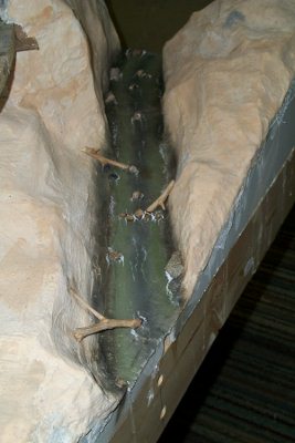
Here is a better shot of "Two Tired Creek" from the 'other' end located on the 'other' long side opposite all the other pictures.  Marvin has done a really great job with the coloring and texture, using many of the artistic skills he uses on his original PRR railroad paintings.


Now, just a couple thoughts on the past couple days work.  Corrugated cardboard strips can be cut in two ways; LENGTHWISE, along with the corrugations and CROSSWISE, across the corrugations.  Lengthwise produces a stronger strip that I prefer for the vertical supports.  Crosswise produces a weaker, but more flexible strip that I like to use in a more or less horizontal position to interweave between the vertical strips.  To increase the flexibility I pull the strips over the edge of the table from both sides.  I also do it with my fingers, but watch out for paper cuts.


This will be the road passing under the track to connect the upper level (maybe I will call it 'Overton' or 'Highland') to the future 2'x8' extension with yard, engine facilities and maybe some industries and staging.


This time I tinted the water that I wet the plaster cloth with.  I mixed several colors to get something of a ground color.  It is not as dark as I would like but will prevent the white spots if chipped or scrapped.  If you work the plaster cloth with your wet fingers or foam brush it will begin to blend and cover the course 'cloth' weave.  Saturday I will add the second coat of cloth and the following Tuesday begin a couple coats of Light Weight Spackle.  I color and dilute the spackle with water to make a thick, soupy consistency and apply with a 2' foam brush and try to hide cloth details.  To help hide the weave and edges I have been 'stippling' the spackle coat using the side of a 2" foam brush to quickly tap the still wet surface, drawing little beads or pimples of spackle.  I am still not really happy with the results, but does do away with the dull smoothness of just brushed spackle.

Hopefully more-useful info for the next post.


Armchair


Sunday, September 9, 2012

LO#12 - Creating Hills

How high are the hills?  How deep the cuts?  Last week I got the hot glue gun going, cut a lot of cardboard strips and spent 5 hours putting it all together along the 10 foot side of the layout.

Tunnels need BIG hills to look real.    
  
Now that is a HILL!
And this is a deep cut revealing Marvins head.
After a week to think about it, the skinny cross section of the hill needed to be dealt with by lowering the height of the front face and the depth of the cut.  Out came the scissors and several inches removed from the hill.  Here are the results to compare.

The hill is still big enough to look real.


The cut looks better, even without Marvins head.  And the branch has a nice cut also.  I like cuts!


While I was working on the long side of the layout, Marvin was working on our creek, a small but wonderful view site.

Marvin has turned my quiet, clean, mountain stream into a littered backwater he calls "Too Tired Creek" in reference to the two old tires half way up and my often expressed condition.      


Tuesday I will be laying out a lot of plaster cloth to give a basic ground level for all the cardboard strips.  I will also be covering the front edge to the lower track.  This will be finished with a fascia board when scenery is finished.

Until Tuesday,

Armchair

Tuesday, August 21, 2012

LO#11 - Touch-up on the Layout

 Before we got started today Marvin took his PRR K4 Pacific out for a run (just to test the track).


While much of the layout is still without any scenery work, the scenic end with rock cuts, tunnel, bridges and more is taking shape and is semi finished.  Before the tunnel portals can be enclosed the ballast must be applied to that area.  I use a small brush, normally used to apply flux to copper fittings before soldering, to apply full strength white glue to the side slopes of the cork roadbed and sprinkle a generous amount of ballast to the area.  I do this for about 6" into the tunnel and an inch or so outside.  After it sets for about 30 minutes I vacuum and collect the excess ballast using an old handkerchief over the hose end where it enters the machine.  By doing the sloped edges first it provides an edge to hold the rest of the ballast in place.  Now I pour ballast over the ties, both between the rails and over the ends of the ties, and use a small foam brush to level the ballast between the rails and level with the tops of the ties all the way to the edge where the ballast was previously glued.  When leveled I mist the ballast with a spray bottle of wet water (a drop or two of dish soap) until wet and then drop white glue diluted half and half with water onto the wet ballast and allow it to soak in.  When set I vacuum the excess as before.

This ballast will be just inside the tunnel portal.


Ballast as seen from outside the tunnel portal.  The edges need to be cleaned up before we close the tunnel.

Marvin has been painting the small creek bed and today started to apply gloss medium to give the surface a wet look. Several more coats ans some assorted debris will be added before it is complete.

Our little creek serves no purpose but to add interest to an empty corner.

Glen Larsen, introduced last week, was put to work lightening the dark gray I applied last week to the rock cuts by adding a coat of light weight shackle thinned with water and some 'sandstone' acrylic paint.

Rock cut and mine area with spur track.

That about does it for this Tuesday's work day.  Stop in again next weekend for more "Exciting" news and views.


Armchair

Sunday, August 12, 2012

LO#10d - Updates on the 5'x10' 8-12-12

Unseen changes are hard to see.  Marvin has painted all the track and turnouts to blend their color and now has to clean out the turnout (switch) points of any stray paint, clean and check, clean and check.

Air brush painted rails and ties to take away the "New" look.


 Our newest 'year round' member is Glen Larsen.  Glen has a backyard shed he hopes to convert into a train room in the near future after clean-out, adding insulation and A/C.

Glen L. is shown here trying out one of his long stored HO engines.

Fellow "Founding Member" Marvin Crim feels the need to run some trains after his long time track laying and wiring efforts.
Marvin is helping Glen L. check another engine from his stored supply.

I, on the other hand, keep my nose to the grind-stone and continue adding ground surface to the layout.

Cardboard strips will change a flat foam sheet into a slopped and textured blasted wall for the mine.


And here is the other side of the blasted wall, all that is left of the original hill.
 
I have been applying the second coat of plaster cloth so white on white doesn't show very well.  The two layers are to give it strength, followed by a couple of colored, flowed and brushed coats of lightweight spackle to create realistic texture.

Slow, but sure progress.  That is the motto.

Armchair

Thursday, August 9, 2012

LO#1a - Layout Track Plan for 5'x10'


Here You see the Original Drawing from Dec. 1967 Model Railroader.  This is shown with the original 4'x8' grid markings.  Most of the recent scenic work with profile boards and plaster cloth has been at the lower part of the plan where the lower track curves under the upper and dives into a tunnel.  This is also where the 3 section truss bridge will be placed.

Sorry about how long to post a track diagram.  I just figured how to import images from email today, I guess you can teach an old dog new tricks.  More later.

Armchair

Sunday, July 8, 2012

LO#10c - More "How To"

Not a lot of visible progress again this week.  I missed the Saturday meeting as I had to take the wife to her heart doctor for test results.  She passed them all and can wait another year and a half to return.

The recent pictures showed a lot of cardboard strips and profile boards.  I again started with Elmers yellow carpenters wood glue as that is what I am familiar with.  It  grips quickly and sets up in just minutes.

:

But, I found that hot glue is even quicker, just look out or you get burned fingers.  The profile boards were trimmed to fit using a single edge blade or utility knife.  I like to support the boards from below and at least one edge or from 2 edges.  Glue will run down the corrugations so build it up along the paper edges.  Hot glue will build up better if you give it a good squeeze.  And NOTE: hot glue doesn't work well on foam, it just melts the foam.  I made a lattes of strips as you see on the right and just connected the profiles on the left.  The cardboard frame gets quite stiff after the intersections are glued.  Of course this is all to support the plaster cloth that should be coming in the next week.


 The outside profile boards were started with white paper sided foam core board as seen on the right above.  I spread glue along the bottom edge and lined it up with the outside edge of the frame.  When my cheap supply ran out I switch to cardboard boxes, but found I had to add strips on the outside surfaces to hold in position.  These strips can be plainly seen on the brown left side boards.  After the internal structure of profile boards and strips are glued in place I am able to remove the strips.  To ensure the outside boards remain vertical and inline with the frame I check it with a vertical surface from time to time.

The final fascia will be 1/8" or 1/4" tempered hardboard which will start at the lower edge of the frame board and be trimmed to the top edge of the outer profile boards.  I plan to attach it with glue and screws, maybe set in finishing washers.

I have to paint and ballast the track just inside the tunnel and maybe a few other places that will not be accessible after the plaster cloth is applied.   I will also have to form the inside walls and roof of the tunnel for several inches inside the tunnel that will be visible.  I will also have to cover all the track in the area to protect it from plaster and paint during scenery work.

My homework for the near future will be creating two tunnel portals, a plate girder bridge for the mine track entrance, and 3 inside and outside trusses for the curved 3 section bridge.  Here are some prototypes.

This sample was made from foam board, same as foam core, but without the paper surfaces.  I simply used a dull point to scribe the stone outlines and stained the whole thing with light brown or dark tan, take your pick.


This truss is built of 3/64" square bass wood with card gussets. The real ones will have gussets on both sides and support the cross beams between trusses.  The joint between the center section that meets each end section will be supported by an extended beam reaching out to clear the lower track, one to the inside and one to the outside.  You will see later.

The girders will probably be made of card with a rolled strip for the top.  Not on paper yet, still in my head.

Our next meeting is Tuesday 7-10-2012 and I hope to have a lot more pictures to show.  I lost my camera so these will be taken with my phone.

Till then,

Armchair

LO#10b - More History & Corrections

My friend and fellow RRoY Club member, Marvin C. passed on the correct name and magazine month for our HO layout.  The correct name is Pigeon Creek & Thawville RR and the MR edition is December 1967.

Another item I passed over was how we laid out the curves for the sub-roadbed.  I used a home made beam compass, or trammel, with a hole drilled for a large marker pen at one end and holes drilled and marked on inches through about 30 inches.  You could make your own using a yard stick drilling the pen hole at 1" and holes as required.  Just remember to ADD 1" to your desired radius.

 While I am not doing any of the track laying or wiring I can explain a little of what I have observed.  Marvin solders all rail joints using track joiners for alignment.  We are using Peco Electo-Frog turnouts that are power directing so do not have to power each piece of track, but must power the turnouts from the single (left) end only.  The power is directed whichever way the turnout is thrown, BUT the other two ends must be gaped if power can be fed from  another track, otherwise you have a short.  In this case the turnout is at the beginning of a reverse loop so there is a "section" of track that is isolated inside the loop to allow the mains polarity to be reversed for when the train returns to the main.

The control panel will be located in one of the corners and have provision for one, DC, power pack.  The future extension to a lower yard or town will have provision for a second power pack, but may be controlled from the main panel for 'one man' operation.

Armchair


Tuesday, July 3, 2012

LO#10a - How We Are Building the Layout

As I review this series I realize that I tell what is happening, but not much how it is happening.  Some of you may be old hands at building layouts and may find this old stuff, but for more recent members of the hobby I hope this will explain some of the techniques Marv and I are using to construct our yet Un-Named, HO railroad.

Marvin found a layout, Pigeon Creek & Thawville RR in Model Railroader Magazine from December, 1967, that he had considered before.  Designed as a 4'x8' he wanted to see how it would look as a 5'x10'.  I redrew the grid lines over a printout of the original to give reference points to a 5'x10'.  Satisfied that it would work I set about designing the frame and developing a bill of material as seen below.


With mutual agreement I proceeded to purchase the material, approximate cost $45.00.  Wanting a more quality source, I used a local lumberyard with 1"x4" straight boards and would cut to our specs. I used some 2"x2" from my own stock to reinforce all the joints as I don't really trust screws into end grain.
The results are below, the early joints were screwed and glued, later ones screwed only.  Some may cringe, but we used drywall screws throughout the construction.  They mostly don't require countersinking in soft woods like pine, but the head will split the wood if used too close to the end of a board.


 At this point we established more parameters;
  • 23" minimum curve radius
  • 1.8% maximum grade
  • 4" minimum center line of track to edge of layout
  • lower level track to be at 4" above the frame to allow below track scenery
  • #6 Peco turnouts on main & #5 on some sidings
  • Code 83 Peco track, later changed to Atlas to withstand handling
  • Laid on cork roadbed
  • 1/2" plywood or chip board sub-roadbed
  • DC control
I brought my 8" band saw to our meeting place at a local church and began cutting curved sub-roadbed.


Below is  the very earliest beginning of the actual track plan.  The silver finish on some curves is on material one of our winter members found at a building site and cost, nothing.  All sub-roadbed joints were reinforced with splice plates on the under side.  Turnout locations were laid out using actual Peco turnouts.  Most were OK, but some had to be realigned when laying track.  If I do it again I will solder about a foot of track to all three legs to ensure the curved leg would properly align with the main and that the turnout is not too close to a curve.  You will also note some added 1"x2" cross member to prevent  excessive twisting 


Risers were made from 1"x4" capped with 1/2" ply to screw sub-roadbed from below (later changed to from above because of old men).

As you will notice in the title, this is LO#10a, meaning I will be bringing several more editions to detail features up through this time.

Stay turned, check back often for our latest exploits.


Armchair


Sunday, June 24, 2012

LO#9 - Creating the Earth

Life would have been simpler if I would have been comfortable with a hill no taller than the tunnel portal.  But, those who follow this blog know I am not that simple.  Today a railroad would simply make a huge, wide, cut or fill, but that removes those tight, scenic views we modelers desire.

Over the last few weeks I have been making a mountain out of a molehill.  There was always a tunnel for the lower reverse loop that is just 5" below a proposed industrial area.  My goal is to construct scenic view sites that highlight only one elevation at a time unless a somewhat realistic profile can be devised.

This earlier photo shows the basic sub-roadbed for the entire HO layout.


As you can see we struggled to gain elevation to clear the lower level while keeping our 1.8% maximum grade.  This would simulate the early days of tinplate, almost everything visible from everywhere.  Today's modelers use view blocks to separate scenes and increase the perceived size of the layout.  This end section of the layout will receive the most attention with bridges, tunnel, mountain, overpass, mine, creek and road.

A few weeks ago I mocked in the tunnel portal visible from the long left side in the above photo.


The curved white piece above the portal simulates the mountain that requires the tunnel and also blocks the view of the upper level track just 5" above.

Just a couple of feet along the main we will use an underpass or bridge to allow the mine entrance track to logically pass just below the upper main.


As both tracks reach the end of the layout they curve to the left with the lower passing under the upper and running through a deep cut before plunging into the tunnel, obscured by the cardboard wall of the cut.


The upper track will be supported by a three section truss bridge before it runs through its own cut as it skirts around the edge of the mountain.


This next photo shows most of the scenic action in this corner, the lower level tunnel, the 3 section truss bridge, the creek with floating blocks of wood.


The last pic is of my prototype outside truss member.  It will be about 55' HO scale and the inside truss will be about 46'.


I hope you enjoyed the pictures.  Come back often and maybe you might just leave a little comment , if you really want to.  Or not.  As the old country song says " Oh Lord it's hard to be humble when you're  perfect in every way"


Armchair

Saturday, June 16, 2012

LO#8 - Setting the Track in the Ground

The last few weeks have been interesting for me as I try to imagine how the ground laid before we put the sub-roadbed in position.  Marvin has finished the track laying and block wiring, leaving him little to do but run trains, clean up the wire runs and document the block wiring and reverse loop switch positions.

The only ground contour using profile boards I have worked with till now was on the small diorama portrayed in the 10 part Clinic Building a Diorama on this blog last year.


This was the clinic diorama before desert shrubs were added.
The profile boards supporting the sub-roadbed and with twine lacing to support the plaster cloth.


As with the diorama above, this 5'x10' layout is a learning experience for me.  As you follow through the photos past and present you will see a variety of my efforts to use new or different ways to construct scenery.  Also be aware that most of this will have to be removed when we ballast the track and replaced with a more robust support structure.

Last Tuesday I began placing temporary profile boards around the outside edges of the layout.   

I lost my cheap foam-core board sources so have switched to corrugated cardboard boxes at $1.32,  providing 4 pieces 12"x48".
These outside boards and the upper contour will be used together to determine the ground location between those points and provide the degree of cut or fill needed.  The final outside profile boards will probably be 1/4" tempered hardboard screwed to the outside of, and covering, the 1"x4" frame.

This is one of our favorite features, the long 1.8% grade connecting the lower and upper levels.  Marv's train is coming through the upper reverse loop.

The vertical change and sweeping 23" radius curves will provide some really neat viewing angles for passing trains, tunnels and bridges.

A close-up of the above view showing the upper continuous run upper loop, upper reverse loop with train and the start of the 1.8% decent to the lower level.  The slightly curved track will be straightened soon.


This shows most of the 3 section truss bridge over the lower reverse loop leading into the tunnel.  The wood blocks show the contour of a small creek.


The overall view plainly shows the upper reverse loop at the far end

One thing I am trying to avoid is a tunnel portal almost as big as the mountain, something like the highway tunnel under the runway at LAX in California.  So I am building a taller profile to provide a more believable scene.  I will be replacing many of the cardboard strips with profile boards to better control the profile of the cuts.  I may even mockup the surface using paper towels sprayed with a water mist to lay down to the boards.

Till next week,


Armchair


To help you find earlier posts concerning this Layout build I am providing this List:

LO#1    2-1-2012
LO#2   2-9
LO#3   2-19
LO#4   5-28
LO#5   5-29
LO#6   6-5
LO#7   6-9
LO#8   6-19

Find the week date on the right hand side and click to go to the posts during that week. 


Saturday, June 9, 2012

LO#7 - First Train Runs!

The time was 10:50 am, Saturday, June 9, 2012.  Marv eased the first train into the upper loop allowing continuous running and ending track work for the day.  All mainline turnouts are in and tested.  All mainline blocks are wired and tested.

No special ceremonies, no champagne, no golden spike, but today marked a big milestone in the building of our clubs yet un-named, 5'x10' layout.  A train traveled from the lower level, up around the far curve into the upper loop and ran continuously for about an hour.  The upper reverse loop has to me completed and track added to a couple sidings, but the heavy lifting is done.

My job continues to be mocking up the complex corner with the three section curved bridge, tunnel and portal, small creek and deep cuts.  This is only temporary and will be replaced with better structure after the final wiring is completed and the track ballasted.

The pictures don't show the latest progress very well but do show a milestone moment for Marv, me and the Rail Roadrunners of Yuma.

Marv is following the first train traveling on the newly completed upper loop track-work that allows continuous running.  The outside track to the right descends to the lower level.


I know it is not too clear, but the complex corner is starting to take shape.  I have never gotten this far on a large layout so most of this is new to me.  I hope to complete the mockup before replacing with the permanent scenery.

So there you have it.  Real progress.  I feel like I am learning a lot about building realistic scenery contour.  If you followed through the earlier clinic "Building a Diorama" this will be something of a continuation.

More next Tuesday!


Armchair

Tuesday, June 5, 2012

LO#6 - Hills and Valleys on the 5'x10'

Track-work is continuing on the Club Layout.  Marv has about 12' of track left to complete the upper loop and about 6' for the upper reverse loop.  He runs trains around the lower reverse loop and up to the upper lever to prove the wiring is correct.

I spend my time roughing out the scenic contour with pieces of foam-core board and cardboard strips, developing cuts, tunnels and bridges required for the track.  My goal is to have hills high enough to realistically require tunnels and rock cuts through the hill contour that continues from above the cuts to beyond the track. As I mock up an area I begin to see a better way to form the contour so the pictures all show a transition of ideas.

Marv looks at his handiwork as his train heads to the big curve and downhill to the lower level.  In the near corner you can see the profile boards with a small creek running from the end to the side.


The train you see in this view will be traveling through a deep cut after I build up the hill to give the tunnel a practical purpose.  The tunnel portal will have retaining walls to each side for the near vertical hillside between the lower and upper track.  Retaining walls will also be required between the lower track and the base.


This corner will be the biggest challenge for me.  The upper track will be going through a three section truss bridge while the lower track skirts above the small creek defined by the "S" shaped board at extreme right.  The lower track will be passing through a deep cut before entering the tunnel.  There will be lots of things to see and several ways to view them.


Marv's train is passing through the deep cut defined by the vertical foam-core board on the left and the cardboard strips to the right.  The tunnel portal is barely visible to the left of the foam-core board.  The curved boards beyond the tunnel define the top profile of this somewhat massive hill on this end of the layout.


As soon as the track and wiring is completed and tested we can begin to close up the holes between the tracks and allow the geography to take shape.  Once the rough shape is established out will come the plaster cloth and light weight spackle, followed by stains, paints  ground cover and trees, lots of trees.

Meeting twice a week will speed up the changes so tune in often and pass the word on your Facebook and, if so kind, include the link to the blog  http://armchairmodeling.blogspot.com

Armchair