Saturday, June 9, 2012

LO#7 - First Train Runs!

The time was 10:50 am, Saturday, June 9, 2012.  Marv eased the first train into the upper loop allowing continuous running and ending track work for the day.  All mainline turnouts are in and tested.  All mainline blocks are wired and tested.

No special ceremonies, no champagne, no golden spike, but today marked a big milestone in the building of our clubs yet un-named, 5'x10' layout.  A train traveled from the lower level, up around the far curve into the upper loop and ran continuously for about an hour.  The upper reverse loop has to me completed and track added to a couple sidings, but the heavy lifting is done.

My job continues to be mocking up the complex corner with the three section curved bridge, tunnel and portal, small creek and deep cuts.  This is only temporary and will be replaced with better structure after the final wiring is completed and the track ballasted.

The pictures don't show the latest progress very well but do show a milestone moment for Marv, me and the Rail Roadrunners of Yuma.

Marv is following the first train traveling on the newly completed upper loop track-work that allows continuous running.  The outside track to the right descends to the lower level.


I know it is not too clear, but the complex corner is starting to take shape.  I have never gotten this far on a large layout so most of this is new to me.  I hope to complete the mockup before replacing with the permanent scenery.

So there you have it.  Real progress.  I feel like I am learning a lot about building realistic scenery contour.  If you followed through the earlier clinic "Building a Diorama" this will be something of a continuation.

More next Tuesday!


Armchair

Tuesday, June 5, 2012

LO#6 - Hills and Valleys on the 5'x10'

Track-work is continuing on the Club Layout.  Marv has about 12' of track left to complete the upper loop and about 6' for the upper reverse loop.  He runs trains around the lower reverse loop and up to the upper lever to prove the wiring is correct.

I spend my time roughing out the scenic contour with pieces of foam-core board and cardboard strips, developing cuts, tunnels and bridges required for the track.  My goal is to have hills high enough to realistically require tunnels and rock cuts through the hill contour that continues from above the cuts to beyond the track. As I mock up an area I begin to see a better way to form the contour so the pictures all show a transition of ideas.

Marv looks at his handiwork as his train heads to the big curve and downhill to the lower level.  In the near corner you can see the profile boards with a small creek running from the end to the side.


The train you see in this view will be traveling through a deep cut after I build up the hill to give the tunnel a practical purpose.  The tunnel portal will have retaining walls to each side for the near vertical hillside between the lower and upper track.  Retaining walls will also be required between the lower track and the base.


This corner will be the biggest challenge for me.  The upper track will be going through a three section truss bridge while the lower track skirts above the small creek defined by the "S" shaped board at extreme right.  The lower track will be passing through a deep cut before entering the tunnel.  There will be lots of things to see and several ways to view them.


Marv's train is passing through the deep cut defined by the vertical foam-core board on the left and the cardboard strips to the right.  The tunnel portal is barely visible to the left of the foam-core board.  The curved boards beyond the tunnel define the top profile of this somewhat massive hill on this end of the layout.


As soon as the track and wiring is completed and tested we can begin to close up the holes between the tracks and allow the geography to take shape.  Once the rough shape is established out will come the plaster cloth and light weight spackle, followed by stains, paints  ground cover and trees, lots of trees.

Meeting twice a week will speed up the changes so tune in often and pass the word on your Facebook and, if so kind, include the link to the blog  http://armchairmodeling.blogspot.com

Armchair

Tuesday, May 29, 2012

LO#5 - Tunnel Portals and Underpass

Yesterday I promised some pics of scenery profiles and details.  To create an upper level on an HO 5'x10' layout with 23" curves the track gets pushed near the edge all around.  This creates a situation where the layout is literally cut out of the earth and placed on a table.

The lower level is visible only on one side (front) and one end.  The far (back) side will have profile boards mostly up at the upper level.  The other end will have the transition from lower to upper levels including the curved turnout leading to an extension for yard and industry.

My goal is to get enough scenery above the upper level track to justify a tunnel for the reverse loop yet sloping enough to display the lower track.

The following pictures show the mockups of tunnel portals and underpass.

This is the portal on the front side with mockup scenery above.

An underpass allows access to the mine area spur.
 
This is the tunnel portal visible from the end, looking over the three section truss bridge.

Marv will have three more turnouts and connecting track to install and wire before we can get into scenery.  Some of this had to be removed to accommodate the track crew, but I now have some documentation to remind me in the future.  Another two weeks and we should be able to run trains on all the main line, top and bottom.  The fun begins!

Armchair

Monday, May 28, 2012

LO#4 - Our Summer Jobs - Layout Progress

With Summer here in Yuma and winter visitors home to cooler climes, it is just Marv and me working on the 5'x10' layout.  I have all the cork roadbed down and Marv is laying track.  He has one reverse loop and 2 turnouts down and wired, working on the curved turnout and 4 more on the upper level.
I am faking in some scenery contour with foam core board and cardboard strips, tunnel portals and bridges so we will see what we have to build in the near future.  The actual industries and scenes are still in flux.
Marv and I are meeting twice a week now, Tuesday and Saturday to make a bit more progress.  I will get more pics tomorrow.


The picture is just a reminder of what it looked like several weeks ago.  More tomorrow.

Armchair

Tuesday, May 15, 2012

Having Fun With On30 - I Try Narrow Gauge


As a model railroader, I have been in HO Scale, 1:87, since the early 1960's.  While I always loved narrow gauge, HOn3, 3 feet between the rails, was always too delicate and too expensive.  Then a few months ago I met On30, O Scale, 1:48, 30 inch gauge.  This is the narrow gauge equivalent to Lionel O Scale 3 rail trains, but runs on standard HO gauge, 2 rail track.  Model railroaders jumped at the chance to build equipment using the readily  HO mechanisms and track.

On30 became even more popular some years ago when Bachmann brought out a line of well detailed, but inexpensive, locomotives and cars.  In recent years this scale and gauge has been exploited by several specialty "Mints" releasing various "Theme" trains on monthly subscriptions.  While the detail is similar to the original models, the color schemes are a bit too gaudy for serious modelers without repainting.  A lot of these are being offered on the auction sites for quite reasonable prices.

A colorful train running around 18" radius and card model buildings at a Christmas showing.
 The train above was purchased on the auction site for less than $15 + shipping.  It is running on my 4'x4' HO layout with two circles of track, 22" radius & 18" radius.

Wednesday, May 9, 2012

Let's Build a 3D Card Model - Step 4 -- Conclusion

If you have been working along with the first 3 Steps you will have four walls and two roof sections.  Now is the time to do any cleanup around the door and window openings.  Check the corners for fuzzy card residue and use your knife blade to remove. 

Front wall with cutouts complete and tabs folded'

The two end walls have no cutouts so just fold the tabs.
Take a lead pencil, and from the INSIDE of the door and window openings, use the side of the lead to darken the paper and card backing to eliminate any white spots.  Do it from the inside so if the pencil slips you won't get pencil marks down the face of the building.  Ask me how I know!  Also apply lead to all the edges of the walls and roof sections from the INSIDE faces.


A few problems came up during the assembly:
a.  The chimney is too small to fold easily when glued to the card backing so if you have not glued your sheets to the card cut out the area around it and set it aside.  The best solution is to print the sheet with the chimney and fold as a single sheet of paper.
b.  The tab on the one roof section is too thick to match the other side so I cut the tab off and made a paper hinge to replace the tab. Lay the two roof sections peak to peak (check the position for the chimney) and glue the hinge in position over the seam.
c.  This would be a good time to do something I forgot to do, paint the underside of the roof sections that overhang the walls.  Almost any dark color, tan, brown, black, looks better than the face of the cereal box.
d.  Some of the tabs (mostly at the ground level) need the corners trimmed back about a 1/16" and then at 45 degrees to clear he  tab of the of the mating wall.  I used a small diagonal cutter to trim the tabs, but the knife will do the job just as well.

 To mount the doors and windows recessed into the wall we need to add some spacer strips to the inside of the walls and mounting strips to the back side of the doors and windows. To do this use some of the left over mounted print and cut 4 or 5 strips about 1/8" x 3", holding the steel rule tightly to prevent slipping.

1/8" x 3" strips for mounting the doors and windows.


Study the picture below for a moment.
Using the strips we just cut, trim and glue them to the inside surface surrounding the cutouts, both sides of the 2 big center board wall cutouts, both sides and top of the 4 blue doors cutouts and both sides, top and bottom of the 2 window cutouts.  Align the strips to the edges of the cutouts and use just a couple little dabs of glue.  These strips create the spacing to recess the doors and windows.

Now cut strips about 1/4" longer than the width of the doors and windows and mount to the rear (inside) surfaces with a single little dab of glue.

Spacer strips and mounting strips applied and drying.
When the glue had dried dry-fit the windows and doors in the cutouts and behind the spacer strips.  This is the time to ensure you have the right item in the right cutout.  Also note that some have top or bottom details that must be correct; the big center board walls have weathering at the bottom edge and one window has a person's silhouette.  When satisfied with the fit and location, mount the cutout items with a single dab of glue on the 4 protruding tabs and set aside to dry.
Doors and window located and mounted in the wall sections.

At this time you can take a look at the 3D effect you have created.  If you built the model in Step 1 compare the flat surface with the recessed surfaces.

We are now going to do the final dry-fit of the 4 walls.  check each corner to ensure the tabs don't overlap or interfere with each other.  If you have a small desk drawer you can use the inside corner of it to ensure a square corner and same height where two walls meet.  I cut several right angle triangles with about 3/4" long legs. and glued them as gussets in the corners to keep the structure square.

With the 4 walls complete, fit the roof to the walls and determine how much overhand on each end.  Apply glue along the tabs, locate the roof over the peak of the side walls and hold in position pressing on the end wall tabs to let the glue tack.  Now turn the house over on the roof and press the side wall tabs against the roof, both sides.

The chimney is the last item to mount in the location noted on the roof panels.  Scrape a little glue to the inside of the mounting edges and a very little to the edges and set in place.

Here I am comparing the 3D model with the flat surface model I built earlier.

You now have a substantial model in HO scale, 1:87.  Place it on your HO model railroad, or on the shelf for others to admire.  I am already thinking of a little diorama with a split rail fence, outhouse, well, woodpile, maybe a cow or pig...............

Till next time,

Armchair


Saturday, May 5, 2012

Let's Build a 3D Card Model - Step 3 -- Cutout Details

In Step 1 we downloaded the two free colored  sheets of the Thomas Lincoln house and built the house per the instructions provided.

In Step 2 we mounted the second set of printed sheets to the cereal box card stock.

In step 3 we will begin cutting out the several sections of the building.

Just a reminder, this is a first for me, cutting out details such as doors and windows and mounting them set back from the outside surface of the model, creating a 3D appearance.  Do not expect perfection, we will be learning together.

WARNING:  Tools used in card modeling can cause injuries if not used carefully.  Children should proceed only under adult supervision!

Tools:  In the photo below you will see the tools needed for this part of the project: a knife handle with a #11 blade or other knives with break off or replaceable blades, a steel rule toguide the knife blade, a small hammer and nail or straight pin to locate the corners of the doors and windows.  Not shown is a letter opener I use to scribe the fold lines.

Tools and mounted, printed sheet, ready to make your 3D model.

Note:  You may wish to practice the several action OP's described below using the extra space around the sheet.

OP. #1  Scribe the fold lines with the letter opener using the steel rule to guide and ensure straight fold lines.  Without the cardboard backing this could be done with 3 or 4 firm strokes, but with the card backing I found I also needed to use the knife blade to cut about half way through the backing.

OP. #2  Place the mounted sheet over a scrap of cardboard or foam core to protect the table surface.  Carefully place the point of the nail or pin at the corner of each door or window detail to be removed and use just a light tap of the hammer to pierce about half way through the cardboard backing, just enough for you to locate the point of the knife blade.

OP. #3  Place the print on your cutting board and use a steel rule to locate the cutting line between two corner punches, check each location with the blade point, and while holding the steel rule firmly, lightly stroke the knife blade between the two punches several times. Repeat for each side of the door or window and, with firmer strokes continue cutting until the door is cut free.


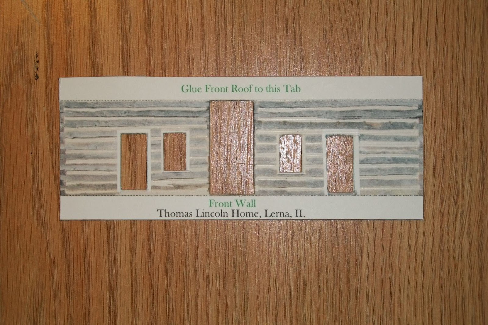
Two doors and windows and the center board wall have been removed.

OP.#4  After all the scribing and cutting is complete remove each part by carefully cutting around the part being sure to NOT cut off the fold tabs.  This will leave you with a part shown below.


Cutout front detail part before folding the tabs.


OP.#5  Locate the fold lines at a sharp edge and fold tabs down as shown below.  If the tabs don't bend with firm pressure you may have to use the knife to cut a little deeper into the backing sheet.

Front detail with tabs folded down.

Continue with other details, back, sides and roof, until you have all the parts required for the model.

This is one of the end details with tabs folded.


Details ready for adding the recessed doors and windows for a 3D model

In Step 4 we will be adding the recessed doors and windows and maybe some outside raised details.


Armchair